Introduction
Branco motor can be used as a three phase asynchronous inverter capable motor with constant torque for frequency range from 30 to 60Hz, and the rated 50Hz values is shown on the name plate. The rated values of operation figures from selected voltage are shown by option voltage.
Connection:
Output ≤ 3kW shall be connected as star (Y) for 400VOutput > 3kW shall be connected as delta
 for 400V
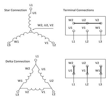
Prescribed use of Branco standard motors according to IEC 60034-5: The standard motors are provided with degree of IP55 protection and can be used in a dusty and damp environment, as for indoor and protected outdoor installation, climate group MODERATE (temperature of coolant -20°C to +40°C) is to be used suitably.
For unprotected outdoor installation or severe climatic conditions (moisture category wet, climate group WORLDWIDE, extremely dusty site conditions, aggressive industrial atmosphere, danger of storm rain and coastal climate, danger of attack by termites, etc), as well as vertical mounting, special protective measures are recommended, such as:
- Protective cowl (for vertical shaft-down motors)
- For vertical shaft-up motors additional bearing seal and flange drainage
- Special paint finish
- Treament of winding with protective moisture-proof vanish
- Anti-condensation heating (possibly winding heating)
- Condensation drain holes
#the corresponding conditions of installation have to be clearly indicated in the order.
Branco motors are totally enclosed and self-ventilated (TEFC) by a bi-directional fan mounted on the NDE of the rotor shaft. The upkeep of care must be constantly taken to ensure the adequate clearance for maximum air flow and cooling. If the optional external fan is used, the correct circulation of air flow must be taken into consideration for a proper cooling.
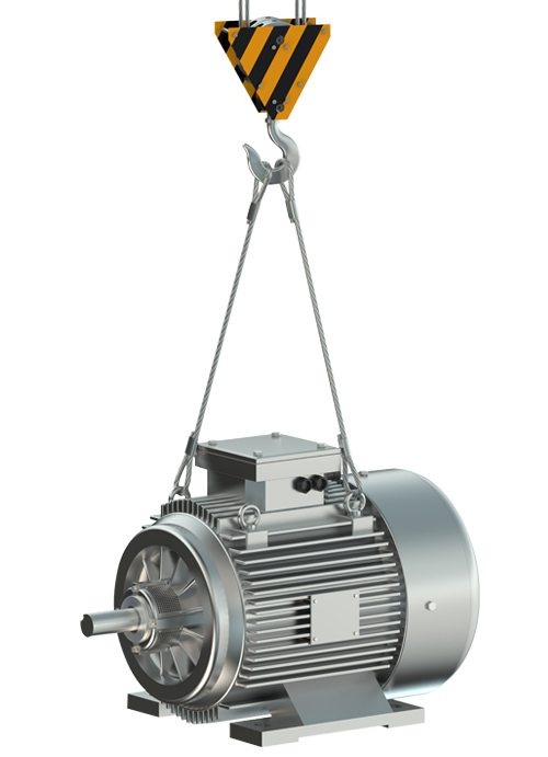
Handling and storage
When lifting the motors, always uses the lifting eyes provided. Make sure that the lifting eyes are installed correctly and tightened prior to lifting the motor. Never lift a motor using the motor shaft and fan cowling. In addition, care must be taken during lifting and lowering of the motor to avoid any shocks or vibrations which may result in bearing damages.
Storage
It is highly recommended that all motors to be stored in a dry, dust free environment and free of excessive vibrations. The relative humidity of air should be less than 60%. Covers or tarpaulins which are used to protect the equipment against the weather must not make contact with the surface of the motor for air circulation. The service life of the motor can be considerably reduced if the storage period extends beyond 2 years in environment with high moisture and dirt. The insulation resistance of the winding should be measured to determine the condition as well as the wellbeing of the motor prior to installation and start-up.
Machines surfaces are treated at the factory with anti-corrosive process. However, these surfaces necessarily should be retreated during storage. It is recommended that the motor shaft is rotated by hand in a frequent basis to ensure even grease distribution.
Sealed type DE/NDE bearing is recommended to be replaced if storage has exceeded 2 years form date of motor purchase. If the motors are re-grease capable (with grease nipper), then the recommendation is to replace the grease after 2 years of storage.
Commissioning
Safety Rules
The five safety rules according to EN 50110-1 to unsure
"working in no-voltage state":
- Disconnect the system including the auxiliary circuits, anti-condensation heating.
- Logout so that the system cannot be switched on again.
- Verify whether equipment is essentially in a non-voltage condition.
- Verify the Ground and short circuit.
- Cover or fence off the adjacent components that are still live.

Lifting eyes are screwed in place and must be tightened. If the motor is installed vertically with the DE shaft facing downwards, a protective canopy is recommended to cover the cowling fan. This canopy is necessary to prevent the ingress of water and foreign objects that may inhibit proper fan operation.
If the DE shaft is facing upwards, a seemly protective measure is recommended to be taken to prevent liquids from entering the motor windings via the shaft. Care must be taken to install the motor on a solid foundation so as to avoid excessive vibration which may result in premature bearing damage.
To ensure a quiet and vibration free operation, proper axial and radial alignment of a balanced transmission element (coupling, pulleys, fans, gear box, etc.) is crucially essential. The transmission and coupling elements are required to be half-key balanced to ensure a vibration free operation. Coupling and motor temperature consideration must be taken into account during alignment of the transmission. Key must be removed from the motor shaft prior to starting if no transmission is coupled. It is recommended to consult the alignment details from transmission element supplier, and check on frequent basis.
After period of storage or standstill (≥ 3 months), the insulation resistance between phases, and phase to ground should be measured before applying power at start-up. The minimum insulation resistant between new, cleaned windings with reference to ground is 200 M Ω.
Normal failure and corrective measures on insulation resistance:
Cause: Due to high humidity.
Correction: Windings oven bake.
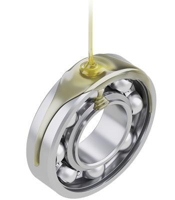
Accessories Maintenance
- Motors of frame sizes 80-132 are fitted with life-lubricated bearings.
- Motors of frame size 160-355 are fitted with open bearings and regressing device. Depending on the motor usage, open bearing must re-grease on schedule.
Extended storage period, excessive vibrations and high humidity levels will reduce the useful life of bearing and bearing grease. For sealed or re-grease capable bearing, it is recommended that permanently lubricated bearings should be replaced after 24 months of storage.
As bearings near the end of their useful lifespan, the vibration and noise levels of the motor will increase substantially.
| Frame Size | DE | NDE | Re-greasing period hours for operating temperatures up to 70°C | Quantity of grease in bearing chamber | ||
| 2 POLE | 4 POLE | 6 POLE | grams | |||
| 160 | 6309 C3 | 6309 C3 | 6000 | 12000 | 18000 | 13 |
| 180 | 6311 C3 | 6311 C3 | 4000 | 11000 | 16000 | 15 |
| 200 | 6312 C3 | 6312 C3 | 3500 | 8500 | 13000 | 20 |
| 225 | 6313 C3 | 6313 C3 | 3000 | 6000 | 9000 | 22 |
| 250 | 6314 C3 | 6314 C3 | 2000 | 5000 | 8000 | 23 |
| 280 2P | 6314 C3 | 6314 C3 | 1200 | - | - | 30 |
| 280 4-8P | 6317 C3 | 6317 C3 | - | 4000 | 6000 | 30 |
| 315 2P | 6316 C3 | 6316 C3 | 1200 | - | - | 30 |
| 315 4-8P | N319 | 6319 C3 | - | 2000 | 3000 | 45 |
| 355 2P | 6319 C3 | 6319 C3 | 1200 | - | - | 30 |
| 355 4-8P | N322 | 6322 C3 | - | 1400 | 2200 | 60 |
After period of storage or standstill (≥ 3 months), the insulation resistance between phases, and phase to ground should be measured before applying power at start-up. The minimum insulation resistant between new, cleaned windings with reference to ground is 200 M Ω.
Normal failure and corrective measures on insulation resistance: